
POWER & BATTERY MANAGEMENT
DC-DC Converter Thermal Derating: Verify Continuous Power in the Installed Equipment
A catalogue power rating is a starting point, not a guarantee of continuous output inside a particular cabinet or vehicle. This thermal derating review connects the rating to the actual installation. To make an engineering decision, identify the exact converter configuration, the worst credible source/load conditions, the heat-removal path, and a configuration-specific derating or test record. Accept the continuous rating only under the documented conditions that match the installation.
Why does a rated converter need a thermal review?
The electrical difference between input and output power is dissipated as heat within the converter and surrounding system. Some losses change with input voltage, output load and temperature; the way heat reaches ambient also depends on the installed construction. A published “rated power” without the associated ambient, airflow, mounting and duty conditions is insufficient to predict the temperature of an integrated assembly. Analog Devices’ thermal design discussion illustrates why power density and a headline efficiency cannot replace a thermal review, but its component temperatures and curves are not VOLUXIN data.
If a verified efficiency is available at one operating point, a first-order loss estimate is P_loss = P_out × (1/η − 1). For a purely hypothetical 1 kW output at an assumed 90% efficiency, the calculation gives approximately 111 W of loss. This is an arithmetic illustration, not a measured VOLUXIN efficiency or product dissipation. Do not use it to choose a heat sink or assert an operating temperature. The actual loss and allowable component temperatures require product-specific evidence.
Define the thermal boundary of the exact installation
Begin with the approved product identity: input platform, actual model and output row, module or enclosed construction, interface/control option, mechanical drawing and document revision. VOLUXIN’s DC-DC catalogue separates module and enclosed options across nominal voltage platforms and notes that family labels do not replace exact input specifications.
Record the measured or designed voltage at the converter terminals over the operating cycle. Identify steady-state extremes separately from surges or faults. List the true output voltage tolerance, continuous load, intermittent demand and overlapping start-up events; the existing auxiliary-load sizing guide owns the detailed load-budget method. Do not repeat that calculation as a substitute for thermal validation.
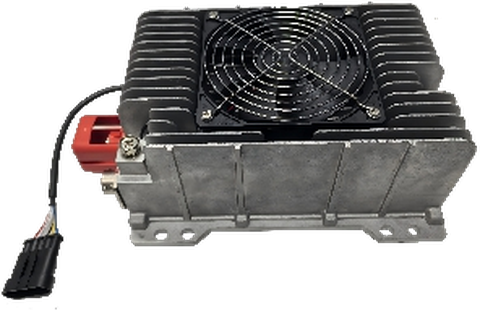
Then specify how the assembly can actually reject heat. For a module, this may include the host interface and mounting contact; for an enclosed design, review installation orientation, exposed surfaces, clearance and any cooling provision specified in the proposed documents. Neither housing type alone establishes a cooling capacity, an ingress-protection rating or an isolation classification. See VOLUXIN’s module versus enclosed guide for the construction decision.
| Requirement to record | Why it matters | Evidence or decision needed |
|---|---|---|
| Exact configuration and drawing revision | Different electrical rows and assemblies may not share a thermal limit. | Configuration-specific specification and installation drawing. |
| Ambient near the mounted converter | Cabinet temperature may differ from room temperature. | Location and operating-temperature profile for the intended duty. |
| Airflow or natural-convection condition | Cooling claims depend on the airflow and obstructions actually present. | Documented cooling assumption and installed-space review. |
| Mounting and heat-transfer interface | Contact, orientation and adjacent structures affect heat flow. | Agreed mounting method and permitted installation conditions. |
| Simultaneous continuous load | A static maximum-load label does not represent every duty profile. | Rail-by-rail load schedule and sustained operating point. |
| Input operating points | Conversion loss may vary across the source range. | Minimum, nominal and maximum input test points as applicable. |
| Acceptance measurement | A pass/fail statement needs a test method and limit. | Probe/sensor position, stabilization criterion, allowable temperature and recorded result, agreed by the project team. |
Review thermal derating evidence for the installed converter
Next, compare the evidence with the installed conditions.
For acceptance, thermal derating evidence must match the installed conditions and exact configuration.
A useful derating record identifies what was varied, what remained fixed, and what limit was reached. For example, a curve of permissible output versus ambient at one airflow cannot automatically be applied at zero airflow or in a sealed enclosure. Likewise, a bench-temperature result on an unenclosed sample is not evidence for a mounted product next to another heat source. Ask for the allowable continuous output under the installation’s input, ambient and cooling conditions; where no relevant record exists, plan sample testing rather than inserting a generic percentage margin.
On the 800V enclosed range page, the main listed options have 500–950 V input while the 51 V output row is a 400–750 V catalogue exception. This illustrates why even a thermal test matrix must name the exact output/model row, rather than treating every “800V converter” as one electrical design. The page provides catalogue rated-power entries, but states that continuous capability, temperature derating and cooling require configuration-specific documentation. Do not claim these variants share one thermal curve.
Agree a sample test matrix before approving continuous duty
A sample plan can combine the relevant steady-state input points with the actual continuous output demand and the worst documented ambient/cooling case. Record supply voltage at the converter terminals, output voltage and current, input/output electrical power if available, ambient near the unit, mounting condition, time at load, selected temperature points and any protection or power reduction observed. Use the measurement method specified for the final configuration. A test at one corner is not proof of all corners; choose scenarios with the responsible engineer rather than multiplying nominal labels into arbitrary tests.
| Test record field | Fill for the approved project |
|---|---|
| Model / construction / revision | [Confirmed configuration] |
| Input and load operating point | [Measured limits and simultaneously operating loads] |
| Ambient, mounting, cooling | [Installed condition or documented representative setup] |
| Temperatures and stabilization | [Sensor locations, method and agreed criterion] |
| Allowed continuous output / acceptance | [Configuration-specific limit and source document] |
| Observation and disposition | [Measured result, deviation, reviewer and approval date] |
VOLUXIN’s manufacturing and evaluation overview explicitly frames output, efficiency, temperature rise and protection checks as project-specific topics whose conditions and acceptance records must be agreed. A generic article is not a substitute for an approved drawing or test report.
What should an OEM request in the quotation package?
Request the exact ordering configuration and electrical/thermal specification; mounting and connection drawing; documented cooling assumptions or derating information; available sample evaluation records; and the agreed acceptance process if repeat production is planned. State what is not yet known. Discuss the configuration with VOLUXIN using the equipment’s actual input range, output loads, installation and requested evidence.
Frequently asked questions
Does “1 kW rated” mean 1 kW continuously in a sealed cabinet?
Not from the label alone. Confirm the configuration-specific continuous-duty conditions and test at representative cabinet temperatures and cooling conditions before accepting that claim.
Can I apply a derating curve from a different converter family?
No. Use evidence for the exact model, output configuration, mounting and cooling condition. A third-party regulator example can explain the physics but cannot establish a VOLUXIN rating.
Is an enclosed converter automatically thermally self-sufficient?
No. The enclosure is a construction choice; its real heat path and permissible installation conditions still need to be checked against the equipment design.
Is a single efficiency figure enough to calculate installed temperature?
No. Efficiency changes with conditions and only estimates aggregate losses at a stated point. Temperature also depends on where those losses occur and how heat leaves the installed assembly.
What if the supplier has not provided a derating curve?
Agree relevant operating points, measurement locations, acceptance criteria and sample tests. Until those records exist, treat continuous operation in the intended installation as an open engineering question.
References
VOLUXIN DC-DC modules and converters, 800V enclosed range and manufacturing review — site-backed product taxonomy and evidence limits.
Analog Devices, “Real Power Density: 26A μModule Regulator Keeps Cool in Tight Spaces” — published thermal example for a different device.
Texas Instruments TPS82130 datasheet — example of how device-specific thermal and operating data belong to the device datasheet, not to a generic power label.
Tektronix, “Power Supply Testing: Methods and Procedures” — temperature, power and operating-point measurement considerations.
Tell us what your equipment needs.
Share your application, product requirements and any details you have already confirmed. We can then discuss the available options.
Discuss Your Requirements