
POWER & BATTERY MANAGEMENT
AGV & AMR BMS and DC-DC Power Supply Solutions
OEM & CUSTOM PROJECT ENQUIRIES
Planning an AGV battery pack?
Request a custom BMS configuration review for your AGV or AMR. Start with the battery voltage, equipment duty and controller or charger interface; undecided requirements can remain open.
Configuration, sample terms and delivery are agreed for your project. Please start with non-confidential requirements.
An AGV or AMR power system needs a battery management system matched to the pack and a supply arrangement matched to its controllers, sensors and other auxiliary loads. Start with the actual voltage window and operating cycle, then compare the component requirements.
AGV & AMR BMS and DC-DC Power Supply Solutions: selection overview
For an AGV or AMR, define the battery-management requirements and the auxiliary power supply separately. The BMS brief covers the pack, protection and controller interface; the DC-DC brief covers the supply window and each low-voltage robot load.
Where the components fit
Practical agv amr use cases
Use these requirement scenarios to prepare a component brief. They are engineering discussion examples, not completed VOLUXIN customer projects.
| Equipment scenario | Operating situation | What to specify |
|---|---|---|
| Warehouse transport AGV | Loaded acceleration, repeated stops and charging-dock visits | Record propulsion current over a representative loaded route, then separate controller and sensor power from traction. |
| AMR with navigation electronics | Computing, lidar and communications during idle and travel | List each regulated rail, start-up surge and allowable voltage variation; document whether navigation must stay powered while the drive sleeps. |
| Docking and opportunity charging | Short charge sessions between missions | Define charge permission, charger communication and wake-up timing with the vehicle controller; request the interface document before choosing a pack reference. |
Engineering knowledge for component selection
SOC reporting is an interface requirement
State of charge (SOC) helps a robot controller decide when to return to its dock. Ask how SOC is calculated, which messages carry it, how frequently they update and how stale data is handled. A CAN connector alone does not confirm the robot can interpret the BMS messages.
Record idle and wake-up power
A parked robot can keep sensors, networking or a fleet computer active. Provide separate active, idle and sleep load budgets, together with the required wake signal. Evaluate the proposed standby behavior in the complete robot instead of inferring it from a nominal converter rating.
AGV and AMR power architecture and operating states
Separate the mobile robot power brief into traction, navigation, computing, sensors and charging. A robot that moves between docking stations has different operating states: travel, payload handling, stationary computation, charging and maintenance. Record which loads remain enabled in each state rather than using a single nameplate current for the whole robot.
Autonomous guided vehicles and autonomous mobile robots can share battery-management concerns while having different control architectures. Describe the docking contacts, wake-up sequence and loss-of-power behavior. Agree which party owns the charger commands, traction enable and software response before asking for a communication configuration.
AGV battery management system: what to confirm
List the pack chemistry, series count, voltage limits and charging approach. Describe communication with the robot controller, including required message definitions and fault-state behavior. A CAN interface label alone does not establish interoperability with a fleet controller or a docking charger.
Use the BMS selection guide to organize the pack and interface questions, then compare industrial BMS catalogue references. Keep requested functions, published entries and unresolved configuration questions separate in the enquiry.
DC-DC power supply for mobile robots: define the rail budget
Navigation computers, lidar, cameras and control interfaces may require several supply rails. State the allowable output voltage range, start-up demand, steady load, sequencing and required response to brownout. Review the input window at the component terminals, including the operating states where traction demand changes.
Record the minimum and maximum supply values at the proposed component, not only a nominal equipment voltage. Review the DC-DC converter specification guide and DC-DC module versus enclosed converter guide before comparing catalogue construction options.
Mobile robot controller pcb fabrication requirements
For a custom robot interface or power-distribution board, provide mounting geometry, connector keep-outs, isolation boundaries and any impedance-controlled communication routes. Compact routing may justify an HDI review; a conventional multilayer board may be adequate where space and interconnections permit.
Discuss multilayer PCB manufacturing or HDI PCB fabrication with the actual stack-up, board dimensions, laminate, copper requirements, holes, surface finish and inspection notes. The custom PCB manufacturing quote checklist provides the file and procurement inputs. Bare-board fabrication is distinct from component selection, SMT assembly and finished-device testing.
Sample evaluation for AGV and AMR projects
Agree a sample review plan before the order, with the equipment team responsible for defining test conditions and acceptance criteria. The scenarios below are planning examples, not completed customer projects or proof of compatibility.
| Evaluation area | Information and review task |
|---|---|
| Docked robot with computing enabled | Record the power state while charging and confirm which controllers remain active. |
| Robot with changing payload duty | Compare loaded travel, stationary manipulation and idle power demand using the same measurement conditions. |
| Low-battery navigation state | Define how the robot detects reduced available energy and which auxiliary rails must remain available during the agreed response. |
For each evaluation, record the sample configuration, drawing or interface revision, operating conditions and observed result. Request the available datasheet, mechanical drawing and protocol information before integration. Use the component quality and documentation review to clarify which records accompany the proposed supply.
AGV and AMR OEM quotation: scope, cost and schedule
Robot auxiliary rail count, controller communication, docking behavior and cable or enclosure customization can change the scope. Compare evaluation quantities and repeat-production quantities separately; document whether the quoted work includes only components or also configuration-specific information.
Ask the quotation to identify the ordering configuration, quantity, requested documents and unresolved technical points. Confirm whether mechanical, harness, protocol or PCB fabrication requests are included. Compare suppliers using the same brief; a lower price may cover a different scope, interface or evaluation requirement.
For prototype or repeat-production enquiries, state the required sample date and production schedule. Minimum order quantity, customization feasibility and lead time are confirmed individually. The custom component requirements review helps organize the discussion before a configuration is approved.
Avoid common AGV and AMR selection mistakes
- Do not equate a nominal voltage label with a complete battery or converter operating range.
- Do not treat a communication connector as an agreed protocol or controller compatibility statement.
- Do not compare current or power entries without their relevant operating conditions.
- Do not infer an enclosure rating, industry certification or complete-system approval from an application photo.
- Do not assume that a bare PCB manufacturing quote includes assembled electronics or firmware.
Resolve these points in the AGV and AMR component enquiry using the pack, load and installation information already available. Undecided values can be marked for review.
Further AGV and AMR procurement questions
What should an OEM include in a component quote request for AGV and AMR?
Separate the mobile robot power brief into traction, navigation, computing, sensors and charging. A robot that moves between docking stations has different operating states: travel, payload handling, stationary computation, charging and maintenance. Record which loads remain enabled in each state rather than using a single nameplate current for the whole robot. Include the evaluation quantity, expected production volume, target dates and the documents needed to approve the configuration.
Can I request a custom mobile robot controller PCB?
For a custom robot interface or power-distribution board, provide mounting geometry, connector keep-outs, isolation boundaries and any impedance-controlled communication routes. Compact routing may justify an HDI review; a conventional multilayer board may be adequate where space and interconnections permit. Provide stack-up, material, copper, hole, finish and inspection requirements for a bare-board manufacturing review.
How should AGV and AMR sample evaluation be planned?
Record the power state while charging and confirm which controllers remain active. Agree operating conditions and acceptance criteria with the equipment designer. Record the sample configuration and requested datasheet or protocol revision; component supply does not establish complete-system approval.
What affects AGV and AMR component cost and lead time?
Robot auxiliary rail count, controller communication, docking behavior and cable or enclosure customization can change the scope. Compare evaluation quantities and repeat-production quantities separately; document whether the quoted work includes only components or also configuration-specific information. MOQ, customization feasibility and delivery timing are confirmed in the quotation for the agreed scope.
How do I specify DC-DC power supply for mobile robots?
Navigation computers, lidar, cameras and control interfaces may require several supply rails. State the allowable output voltage range, start-up demand, steady load, sequencing and required response to brownout. Review the input window at the component terminals, including the operating states where traction demand changes.
What documents are useful before AGV and AMR integration?
Request the configuration-specific datasheet, mounting and interface drawing, and communication information where applicable. Define the sample acceptance plan with the equipment designer and confirm which documents are available before an order is approved.
Does AGV and AMR PCB fabrication include assembled control electronics?
No. A bare-board quotation covers the agreed PCB fabrication scope. Component sourcing, SMT assembly, firmware and finished-board functional testing need a separate scope review; these pages do not promise turnkey control-electronics supply.
Prepare your OEM component enquiry
Equipment manufacturers, battery-pack integrators and procurement teams can use this checklist to separate known design inputs from questions that still need confirmation.
- A loaded route log with current peaks and their duration
- Minimum and maximum pack voltage during discharge and charging
- CAN or other message definitions, node identification and update timing
- Navigation and networking rails, sleep load and wake-up sequence
- Charger-dock handshakes and agreed fault recovery behavior
Include project stage, evaluation quantity, expected order volume and requested delivery timing. Request the configuration-specific datasheet, mechanical drawing and interface information, then agree sample acceptance criteria. Available customisation and document scope are confirmed for the proposed configuration.
OEM selection questions
What information is needed for a custom AGV BMS enquiry?
Provide chemistry, series count, full pack voltage limits, charge and discharge duty, controller protocol, docking sequence and installation drawing. Include the mission profile and the documents needed for evaluation.
Does an AMR need both a BMS and a DC-DC converter?
The BMS and DC-DC converter perform different roles. A battery-powered AMR needs an appropriate battery-management architecture; a separate converter is needed when an auxiliary load requires a different regulated voltage. Define the actual robot power architecture before selecting components.
Related application guides
Industry background: TI mobile robot BMS design resources. External guidance explains component roles; VOLUXIN ordering specifications and compatibility require separate confirmation.
Battery cells → BMS monitoring and protection → vehicle power distribution
Main DC bus → DC-DC conversion, where needed → auxiliary equipment
This is a functional overview, not a wiring diagram. The BMS and DC-DC converter perform different jobs; matching their nominal voltage labels alone does not establish system compatibility.
Start with the AGV catalogue reference
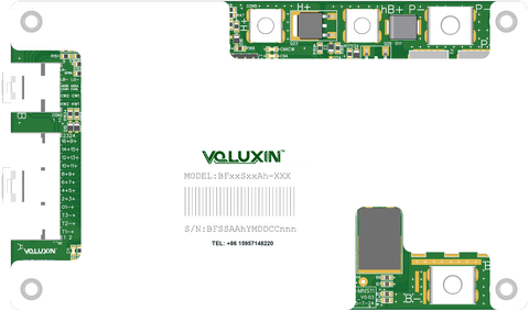
BA48-MNS11 is listed for AGV applications. The catalogue gives 13S or 15S as discrete options, separate charge/discharge ports and a CAN/485 interface entry. It does not establish a 14S option or a chemistry-to-series mapping. Use the model page to review the published entries before discussing the exact battery configuration. AMR use requires a separate application review.
Build the integration brief
| System area | Information to record | Why it affects selection |
|---|---|---|
| Battery | Cell chemistry, exact series count, minimum/maximum pack voltage | Defines the monitoring configuration and operating window. |
| Working cycle | Driving, acceleration, payload, idle and docking/charging periods | A single current figure does not describe all operating states. |
| Communications | Controller protocol, message definitions, baud rate and fault response | A CAN connector does not establish application-level compatibility. |
| Auxiliary loads | Each load voltage, running current and start-up demand | Identifies whether a separate converter and which output are needed. |
| Installation | Available space, mounting, cooling, connectors and service access | Defines the mechanical and thermal review. |
Select auxiliary power by its full input range
Do not select a converter from the battery’s nominal voltage alone. Compare the lowest and highest steady-state supply values, then identify transients separately. Our current DC-DC catalogue starts with a 72V platform whose stated input range is 50–100V; that is not a default recommendation for every AGV battery. If your range falls outside the catalogue options, send a custom requirement.
Explore DC-DC modules and converters, then use the DC-DC selection guide to prepare the load budget. The industrial BMS guide explains how to separate pack, current and protocol questions.
Common questions
Can one BMS be used on both 13S and 15S packs?
The BA48-MNS11 catalogue lists these as discrete options. Confirm the delivered configuration, cell chemistry and settings for the intended pack; do not assume field interchangeability.
Can VOLUXIN customise the interfaces?
Send your controller requirements, connectors and available protocol documentation. Feasibility and the agreed scope are confirmed for the project.
Are the pictured vehicles tested customer installations?
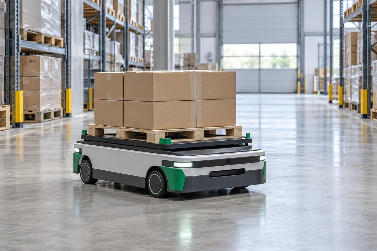
The equipment images illustrate catalogue application areas. They do not demonstrate a delivered customer installation or a validated BMS/converter combination.
Download the requirements worksheet (CSV)
Published by VOLUXIN · Updated 1 October 2026.
CUSTOM PCB FABRICATION
PCB manufacturing for your electronics project
For equipment-specific control, sensing or interface boards, discuss multilayer or HDI PCB fabrication using your design data. Board manufacture and BMS or DC-DC component selection are separate scopes; system performance must be validated in the equipment.
Explore PCB manufacturing → Discuss PCB requirements →VOLUXIN ENGINEERING REFERENCES
Compare products and prepare your technical brief
Read catalogue comparison tables and procurement worksheets online, or download an editable CSV. Reference tables reproduce published entries; worksheets are blank review aids, not test results or final engineering specifications.
| Reference | Purpose |
|---|---|
| BMS requirements worksheet | Pack, load duty, ports, protocol and mechanical information for a custom BMS enquiry. |
| DC-DC load review worksheet | Source window, auxiliary loads, cooling and evaluation conditions. |
VOLUXIN editorial references · Worksheets updated 5 October 2026; catalogue reference tables dated 2 October 2026. BMS/DC-DC values are based on supplied product catalogues; PCB entries use the 2026 fabrication reference. Request configuration-specific drawings, protocols and evaluation records for the quoted scope.
CATALOGUE-BASED SELECTION
AGV battery integration: separate charge paths and controller messages
For an AGV BMS brief, BA48-MNS11 is a handbook starting point: its series options are 13S or 15S, with separate charge/discharge ports and an isolated CAN/485 communication entry. These are discrete pack options, not a continuous 13–15S range.
On small screens, scroll the table horizontally to view every review item.
| Integration topic | What to provide |
|---|---|
| Charging interface | Describe opportunity charging, docking signals and the required charger/BMS handshake. |
| Controller information | List SOC, voltage, current, temperature, alarm and permitted-charge/discharge messages required by the controller. |
| Auxiliary loads | Separate the navigation computer, sensors and control rails from traction demand when defining the DC-DC load brief. |
The model is a catalogue discussion reference, not proof of suitability for a particular vehicle. Agree the battery and equipment configuration before ordering.
Tell us what your equipment needs.
Share your application, product requirements and any details you have already confirmed. We can then discuss the available options.
Discuss Your Requirements