
POWER & BATTERY MANAGEMENT
Choosing a BMS for an Industrial Battery Pack
OEM & CUSTOM PROJECT ENQUIRIES
Ready to discuss a battery management system?
Use this guide to prepare a BMS enquiry, or start with your equipment application and the pack details you already know. Ask for the configuration-specific drawing, interface information and sample evaluation scope.
Request a BMS Configuration Quote
Configuration, sample terms and delivery are agreed for your project. Please start with non-confidential requirements.
Published by VOLUXIN · Updated 30 September 2026. General selection guidance; the agreed configuration-specific documents govern an order.
Choose an industrial battery management system by matching the pack configuration, current paths, operating duty and communication requirements. A nominal battery voltage and one current figure are only the beginning of the specification.
1. Define the battery configuration
Record the cell chemistry, exact series count and permitted pack voltage window together. Series count is the number of cells or cell groups connected in series; a nominal voltage label does not uniquely identify it. Do not infer an approved chemistry from the name of a voltage platform.
For example, the BA48-MNS11 catalogue reference lists 13S or 15S. These are discrete options, not a continuous 13–15S range. Its chemistry mapping remains a configuration question. That distinction should appear in a purchasing brief, rather than being lost in a simplified filter.
2. Describe current over time
| Requirement | Record | Avoid |
|---|---|---|
| Charging | Continuous and peak charge current, duration and temperature | Assuming the discharge limit is also the charge limit. |
| Discharging | Continuous load, transient/peak current and duration | Treating a peak figure as continuous capability. |
| Operating environment | Ambient temperature, cooling and installation | Ignoring the conditions attached to the published value. |
| Connection arrangement | Common or separate charge/discharge paths | Assuming similarly sized boards have the same wiring. |
BF24-MND3 publishes separate 35A discharge and 12A charge entries. In contrast, several other catalogue models have a single continuous-current entry without separated duties. That missing distinction needs confirmation; it is not a reason to invent a second rating.
3. Separate the interface from the protocol
Ask for the electrical interface and the application message specification. A CAN or RS485 entry does not by itself define message identifiers, data interpretation, timing, baud rate or compatibility with your controller. Record the charger, vehicle controller and any display that must exchange information with the BMS. Specify the intended response when communication is interrupted.
The AGV/AMR application brief and material-handling application brief show which equipment conditions to include. For background on the distinction between a CAN physical layer and higher-layer protocols, see Texas Instruments’ CAN physical-layer application report.
4. Check the installation and documents
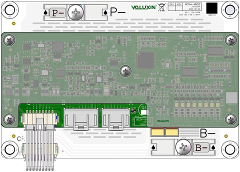
Use a dimensioned drawing to review the mounting points, connector orientation and clearance, not just a photograph. Ask for the exact delivered hardware configuration and document revision. Define the required protection behaviour, settings and verification plan with the responsible integration team before use. This guide does not supply a wiring procedure or validate a safety function.
5. Build a useful shortlist
Compare the confirmed requirements against industrial BMS models. Keep unknown information visible. Two models that share a voltage and current label may differ in ports, interfaces, physical layout or option mapping. Select reference models for a discussion; confirm the ordering code and evaluation scope before ordering.
Common questions
Is a higher-current BMS always the better choice?
A higher label does not establish a better match. The intended pack, charge/discharge paths, operating conditions, communications and mechanical arrangement still need to agree.
Can all series counts between two listed values be used?
Only if the applicable specification supports them. Discrete options such as 13S or 15S must not be expanded to include 14S.
What can I send before I know every requirement?
Provide the equipment type, known pack information, approximate duty and any controller requirements. Mark unknown fields as to be confirmed; use the worksheet to keep those questions visible.
Download the requirements worksheet (CSV)
Next: prepare an enquiry or review our product supply and customisation process.
VOLUXIN ENGINEERING REFERENCES
Compare products and prepare your technical brief
Read catalogue comparison tables and procurement worksheets online, or download an editable CSV. Reference tables reproduce published entries; worksheets are blank review aids, not test results or final engineering specifications.
| Reference | Purpose |
|---|---|
| BMS model comparison | Published series, current, port, interface and envelope entries across 16 models. |
| BMS requirements worksheet | Pack, load duty, ports, protocol and mechanical information for a custom BMS enquiry. |
VOLUXIN editorial references · Worksheets updated 5 October 2026; catalogue reference tables dated 2 October 2026. BMS/DC-DC values are based on supplied product catalogues; PCB entries use the 2026 fabrication reference. Request configuration-specific drawings, protocols and evaluation records for the quoted scope.
Tell us what your equipment needs.
Share your application, product requirements and any details you have already confirmed. We can then discuss the available options.
Discuss Your Requirements